Board and Connectors
There are several hardware versions that are compatible and operated with the same firmware.
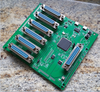
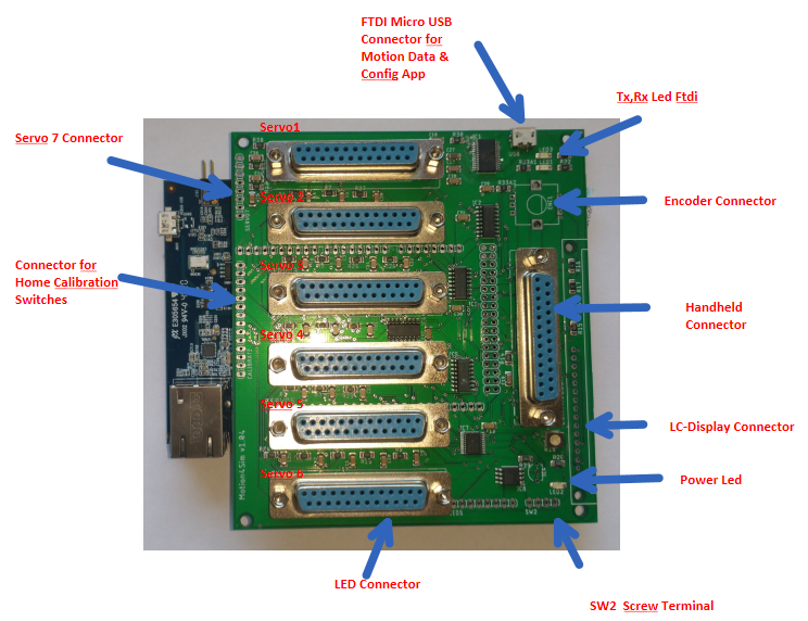
Version 1.04 with SAME70 xpld Board and breakout board for the interfaces Fig.1.
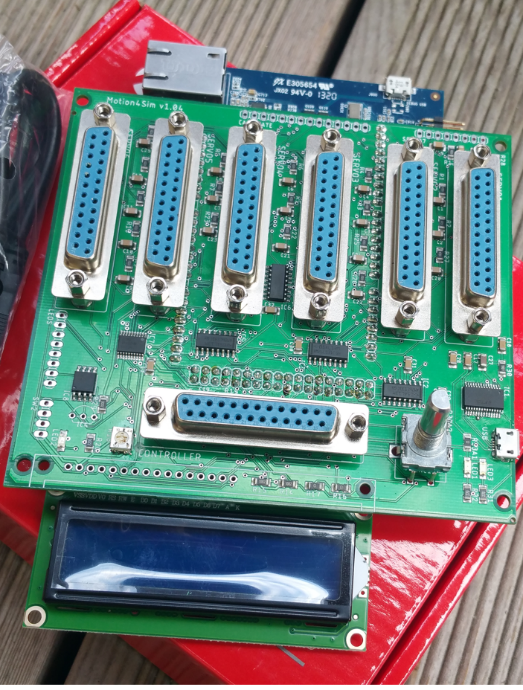
Version 1.05 with ATSAME70 MCU with FTDI or CH340 USB USART Fig.2
Figure 2 M4S Controller v1.05 FTDI Figure 1 M4S Controller V1.04 with display and encoder
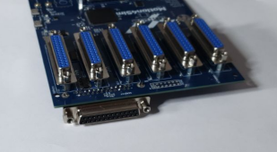
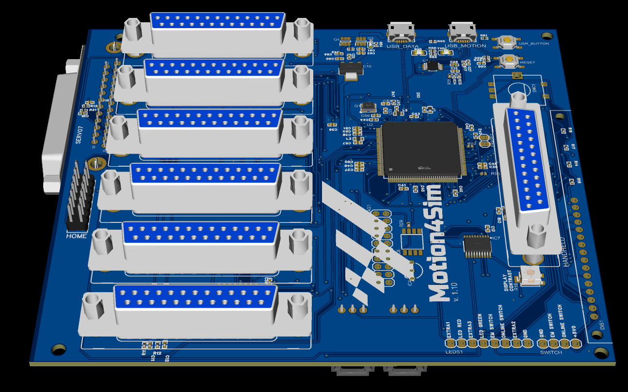
Version 1.08/1.09/1.10 with ATSAME70 MCU with CH340 USB USART and 7 servo connectors Fig.3
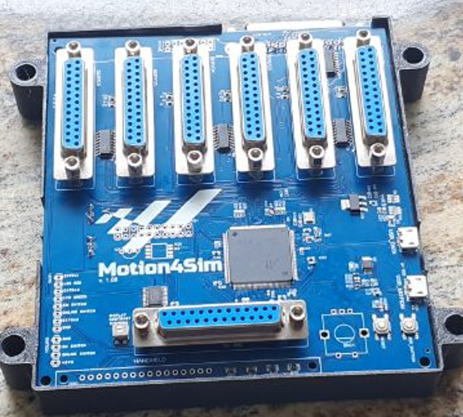
Figure 3 M4S Controller V1.09
In addition, there are additional hardware options. Connector for Brake/Extra01
It is possible to control the system directly on the board using a display and encoder, as shown in Fig.1. Alternatively, the handheld device can be used for remote control. See Fig.3
The handheld device is connected via a SUBD25 male/male cable. The cable can be up to 3m long. 4.5m and 5m long cables have also been successfully tested.
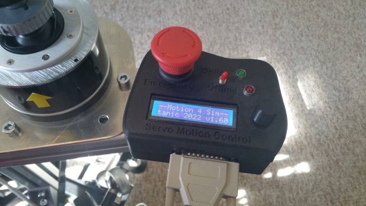
Abbildung 3 Handheld DeviceFigure 3 Handheld Device
There are 6 Sub D25 sockets for connecting 6 AASD servos, as well as a Sub-D25 connector for connecting the handheld device. Soldering points are provided for connecting Servo
1 7. Servo Connector >pcb V1.08
PCB Version 1.04
There are a total of 2 micro USB connectors on the SAM E70 board and one micro USB connector on the Motion4Sim breakout board. There is a reset button and a USr button somewhat hidden on the lower board.
 Übersicht der Anschlüsse:
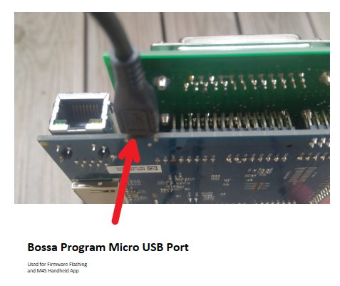
Abbildung 4 v1.04 Micro Usb Port zum Flashen der Firmware
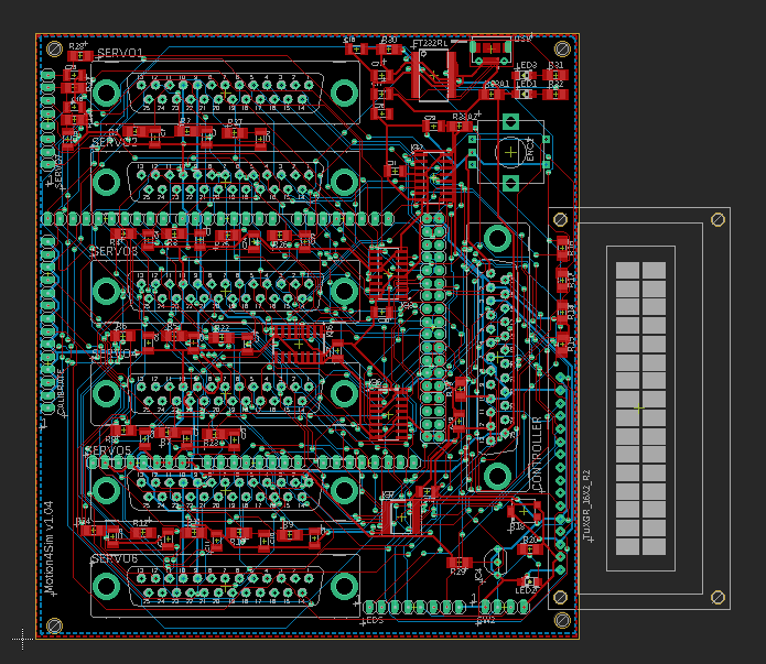
PCB Layout V1.04 – Pinbelegung
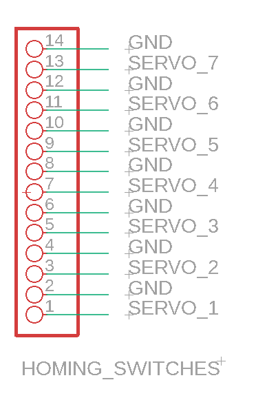
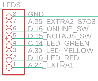

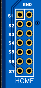
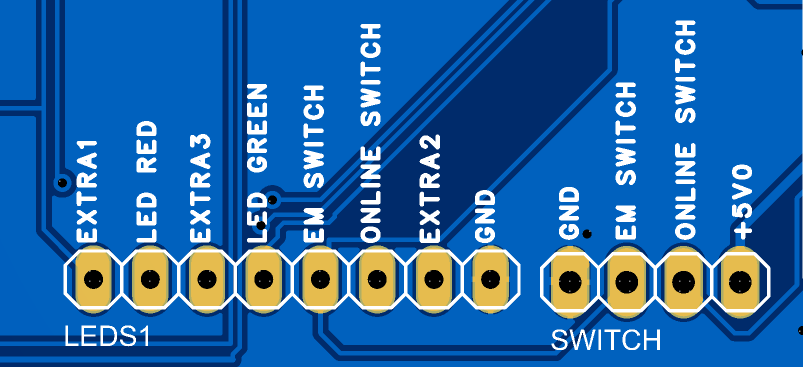
LEDs are operated with 3.3 volts without a current-limiting resistor. The homing switches signal when in contact with GND. The emergency stop switch is “normally closed,” and the online switch is “normally open.” These settings are configurable in the software.LEDS sind mit 3.3 Volt geschalten ohne Vorwiderstand. Die Homing Schalter schalten ihr Signal bei Kontakt zu GND. Der Notaus Schalter ist „normaly closed“ und der Online Switch ist “normaly open“ . Diese Einstellungen sind konfigurierbar in der Software.
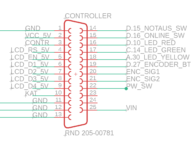
Abbildung 5 DSub25 Handheld Pinout
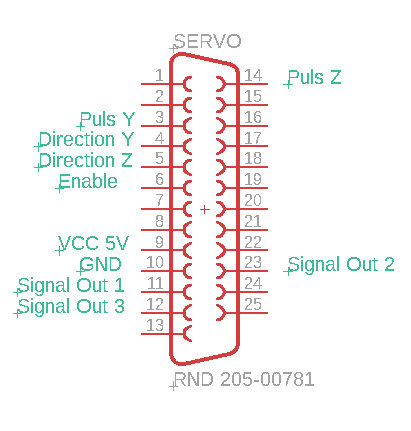
Abbildung 2 DSub25 Servo Connector Pinout
PCB Version 1.05
Overview of the connections.
The same connections as in PCB Version 1.04 are available. There are 6 connections for servo motors, one connection for the handheld device, 2 micro-USB connections, a reset button, a USR button, as well as various connections for LEDs, extra inputs and outputs, and soldering pins for a 7th servo connection and their homing switches. To the left of the handheld device connection, there is a variable resistor with which the brightness of the LCD display can be adjusted.
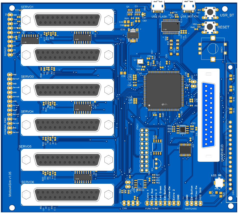
Abbildung 3 PCB v1.05 Übersicht
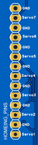
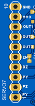
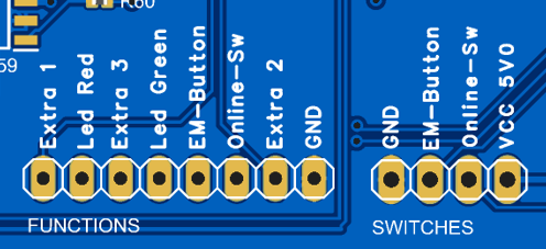
Abbildung 4 Pinout Lötleisten PCB v1.05 im Detail
The delivery of Version 1.05 with display and encoder is equipped with screw terminals at the SW1 connections. Unfortunately, the labeling of Version v1.05 is not implemented as shown in the visual graphics used here. In some delivered boards, some resistors need to be removed to use Servo 7. As of the release of this guide, these resistors are always already removed. These resistors were intended for functions that were not ultimately implemented in the firmware. In case of doubt, please contact support.
Die Pinbelegung der Servo-Anschlüsse und des Handheldes sind unverändert zur vorherigen HW Version. Siehe Abb.
PCB Version 1.08 , 1.09 , 1.10
These versions have a 7th servo connector installed. The functions are compatible with all previous versions. Additionally, the pulse pins of the servo are connected to the hardware timer outputs, allowing for higher pulsing frequencies. Furthermore, sockets for Extra01 and Extra02 are provided but are only installed at the factory upon request.
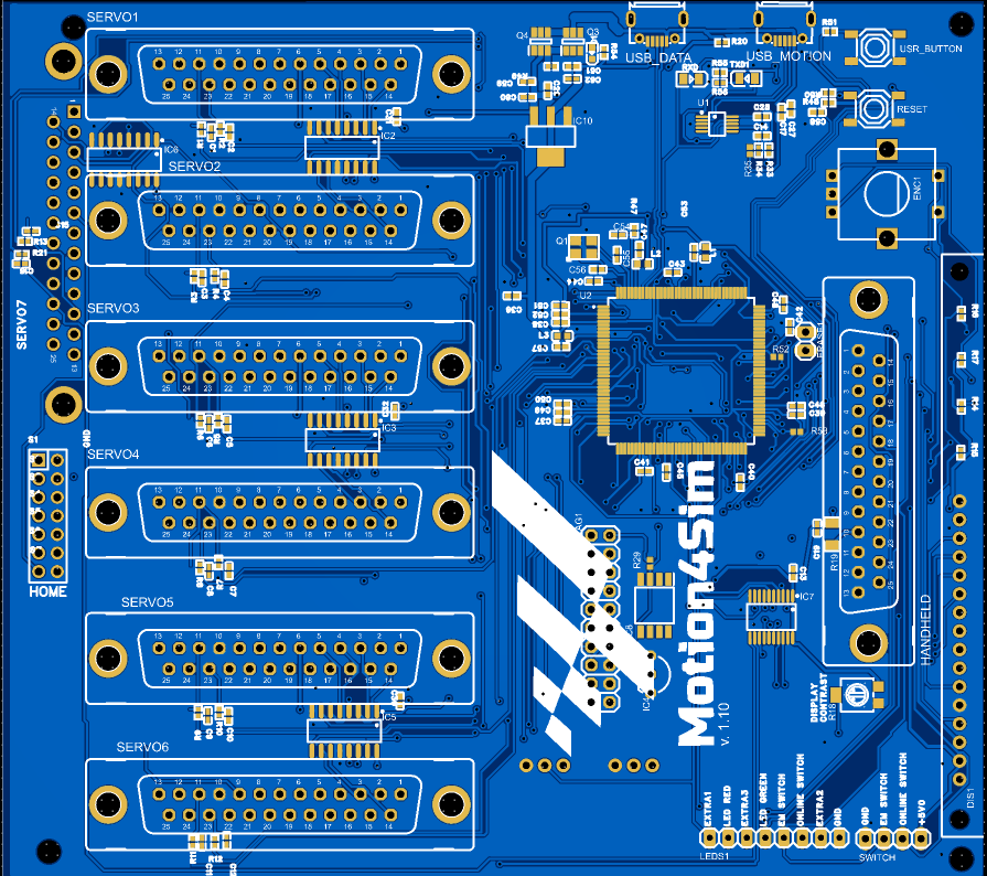
The pin assignment of the servo connectors and the handheld device remains unchanged from the previous hardware version. See the diagram.
To the left of the Dsub connector for the handheld device, there is a potentiometer installed to adjust the brightness of the display.