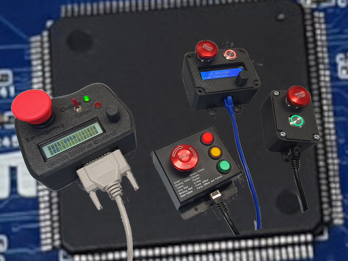

In this article, I will demonstrate how various button boxes can be used with the Motion4Sim controller. There is our in-house button box with online switch or push button and emergency switch. Additionally, there are also button boxes from competitors that can be connected as well. Specifically following the Thanos coupling layout.The Motion4 Sim controller has two ports for remote control devices, button boxes, and handhelds.
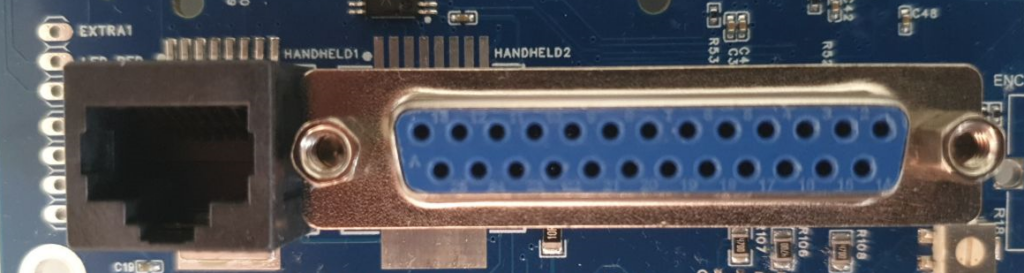
Handheld 1 (Conn 10) is an RJ45 connector, and Handheld 2 (Conn 9) is a female DB25 connector.
In the article represented by the following link, you will find the assignment of the components on the controller.
Below are the pin assignments of the connectors shown.
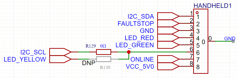
I2C Pins are used from Smart Handheld device only please do not connect them to any other Gnd or Pin or Power source. The I2C bus is shifted to 5-volt level.
VCC_5V0 delivers 5 Volts and can be drawn with 50 mA. The pins for FAULTSTOP(EMERGENCY) , ONLINE (Online Switch or Button) are pulled high with 3V3 directly from the MCU. You can switch them by connecting the signal to GND.
The LEDs Red, Green, and Yellow are also controlled directly by the MCU and can handle a maximum load of 20 milliamperes at a voltage of 3.3 volts. Please note that there are no current-limiting resistors in this line. These must be installed separately if needed. These pins are also directly connected to the MCU. So please be careful, short circuits could damage this pin and potentially impair the MCU’s function. The MCU pins are only 3.3 volts tolerant. 5 volts could also destroy the pin and mcu. For the RJ45 port, regular patch cables can be used upto 3m maybe 5m depending on EMI situation. CAT5 is recommended. For the I2C Smart Handhelds, I recommend using a CAT6 or CAT7 patch cable also upto 5m maybe work but. I2C Handhelds with a cable length of up to 5 meters work in well-shielded conditions. Normally, I2C was not intended for such long data lines, but through code optimization and experimentation, we have found that it can work. However, it is very sensitive to EMI.
By default, the resistor R129 is installed with 0 ohms as a pass-through resistance. The resistor R130 is not installed, so the LED Yellow is not connected to the connector.

How to connect a Other or Thanos Button Box
If you want to use a Thanos button box, for example, this is easily possible. Just connect it. The LEDs will not shine as brightly, as we only operate the LEDs with 3.3 volts. But switches and buttons will work. If you also want to operate the yellow LED, you need to move resistor R129 to resistor R130. Please note that if you need to use a Thanos button box, it is absolutely necessary to remove resistor R129 so that the I2C bus is no longer connected to the LED, with the yellow LED logically then connected to ground. This would lead to a collapse of the I2C bus and the controller will not work properly!
Schema of DB25 Connector Handheld2
Below is the connection diagram of the DB25 connector. The PIN numbers are also printed on the connector.The original M4S handheld can be operated via this connector. Cable lengths of up to 5 meters using well-shielded DB25 cables are possible. The standard length used is 3 meters and works excellently. For 5 meters, it is important to ensure very good cable quality and test them beforehand.
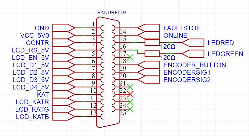
The signals from Faultstop Online, EncoderButton, EncoderSig1, and EncoderSig2 are directly connected to the MCU and are pulled up to 3.3 volts. To generate a signal there, these pins simply need to be shorted to ground. The red and green LEDs are directly connected to the MCU and connected to the Handheld 2 connector via a 120-ohm resistor, allowing the respective 3V3 LEDs to be operated directly. The other pins are suitable for interfacing with an 5V LCD display 16×2, which is operated in 4-bit mode. The connection of an RGB LCD 1602 is also possible.
Furthermore, a small comment, as we can connect multiple handhelds in parallel, once with the RJ45 connector and once with the DB25 connector, it is important to ensure that the buttons and switches are configured as normally open. Otherwise, the switching behavior would interfere with each other.
The DB25 Handheld was previously partially wired with normally closed for the emergency button and the online button. Please keep that in mind when combining it with other button boxes.