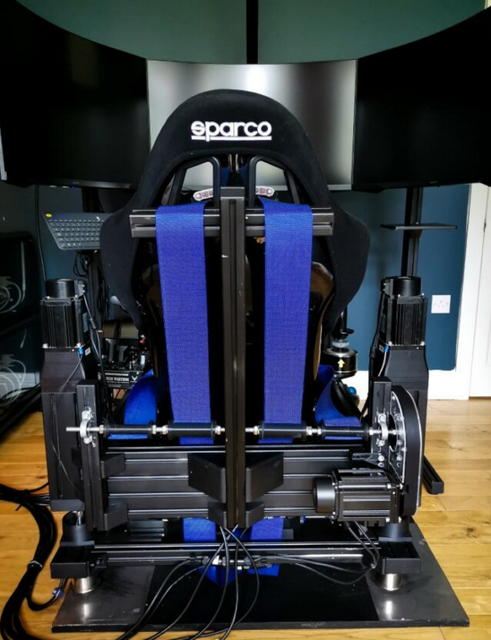
In this post, I will demonstrate how to use and setup the Torque Mode of the AASD servos to operate a belt tensioner, such as the one used by Flag Ghost, for example.
The thanos controller, as well as the m4s controller, currently use the standard step/dir engine to drive the belt against resistance and generate force. This method works very well, but I thought if there is the possibility to operate the servo directly in a torque mode, then let’s give it a try.
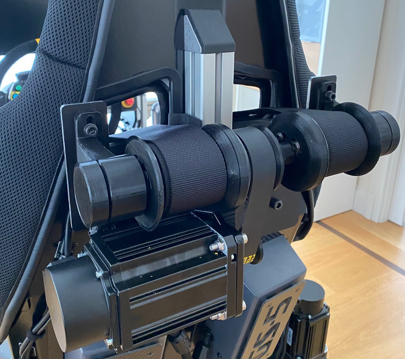
The AASD servo drives internally support an analog -10 to plus 10 volt mode, through which the torque can be directly controlled. This analog signal is delivered on pins 13 and 25 of the DSUB25 connector. You can also refer to the manual for the AOSD servos for more information.
The latest generation of Motion4Sim controllers (from pcb rev 2.03) now supports an analog mode on the 7. actuator connector to generate 0 to 10 volts, which are then sent to the servo drive.
How does it work in practice? It’s relatively simple. When you press the online button to activate the rig online, the other actuators move to their standby position and the analog port is activated. After a brief command to set some voltage to tighten it briefly, it is ready to receive the data from the PC via the voltage provided at the belt.
The M4S controller supports two modes: the Direct Mode and the Position Mode.
In the Direct Mode, the values for the belt are simply scaled to 24 bits at the position of the seventh actor order in the output string. This means 0x000000 for this 3bytes represents no voltage and 0xFFFFFF represents full voltage and full belt tension.
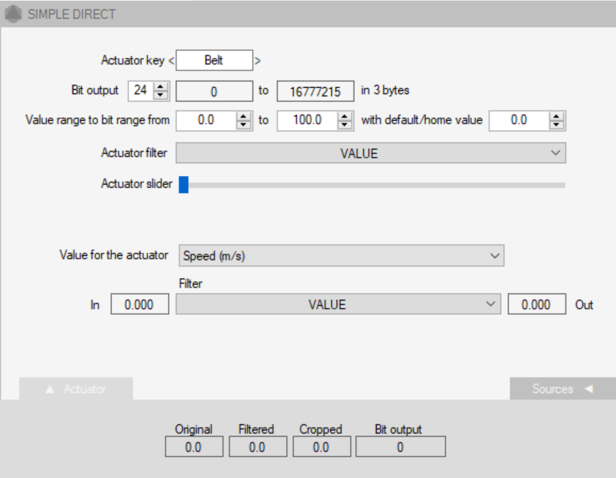
Flypt Mover output string for Direct Mode using belt on actuator 7
<255><255><Axis1a><Axis2a><Axis3a><Axis4a><Axis5a><Axis6a><Belt>000<10><13>
In Position Mode, 32-bit values are transmitted for the first six axes as floats for the 6dof position of the rig, and for the seventh axis, 32 bits are also transmitted as bit scaled. As before, 0x00000000 represents no voltage the belt is loose, and full 32-bit values 0xffffffff represent maximum voltage.
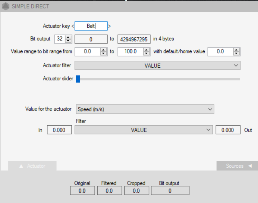
Flypt Mover output string for Position mode using Simple Direct for Belt
<252><252><PSway><PSurge><PHeave><PYaw><PRoll><PPitch><Belt>0000<10><13>
If you use Mover and adjust the strings, please be mindful of the placeholders for zeros for the eighth actuator and the bit sizes for the Direct Mode (24 bits) and the Position Mode (32 bits). Also, make sure to read the manuals for the Direct Mode and the Position Mode.
Setup of the AASD Servo Drive
The settings on the Servo driver adhere to limits and will now be explained below.To reconfigure the servo drive back to the position mode, you only need to set the first register that needs to be changed back to its original value for the position mode. All other values can remain unchanged.
- PN 02 Control mode : 0 (0 Torgue Mode 1 Speed Mode 2 Location Mode (default) )
- PN 191 analogue torgue direction : 0/1 check direction and change to your needs (default is 0)
- PN 198 limit speed during torgue controll : 60 rpm (2500 is default)
- PN 189 Analogue Torgue Command Gain : 30 %/Volt ( 30 default)
- PN 190 Analogue Torgue offset : 0 V (range -1500 – + 1500 mV deafult 0)
The most important value that needs to be set is PN02, where the Control Mode must be changed from Location Mode, which is the default, to the value 0 for Probe Mode. The second value is Analog torgue Drive Direction. Here, you need to decide, depending on how your servo motor is connected, which setting you choose. 0 or 1, clockwise or counterclockwise. This depends on your installation.
PIN 198 limits the speed during the pressure mode. This means that when there is no load on the motor, it rotates at the maximum speed of 2500 revolutions, which is the default setting. However, we do not want the motor to spin that fast. Therefore, we reduce the value to 60. That’s the setting I have chosen. You can also choose a lower or higher setting based on your preference.
With the next value PN 189, you can limit the torque, the maximum force, by specifying how many volts, how many percent of torque per volt should be applied. The default value is 30; if you reduce it to 15, only half of the force will be applied at the maximum value of the bits recieved.
The last value I experimented with is PN190 of the servo settings, specifically the analog torque offset. Here, you can set how the servo should move around the zero point if it already builds up force. Depending on the controller’s power supply, you can adjust the zero point more accurately here and simply experiment. I am using the default setting.
Setup in the Controller
The settings in the controller are relatively simple. It is just to activate, as I will show shortly. It should be mentioned that this feature is only available for Pro Boards. Additionally, note that the torque mode only works when the controller is powered by an external 12-volt 500mA-1A power supply.
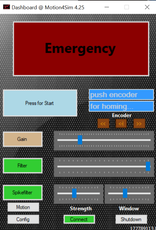
To activate the Belt Torque Mode, connect your servo to the seventh port of the controller using a DB25 cable. Power it up and connect it to the computer via Ethernet or USB, then launch the dashboard.
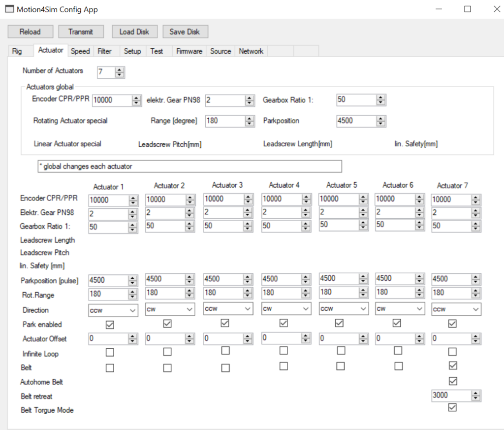
Wait until the Connect button turns green and the controller is connected to the dashboard. Then open the Config page and go to Actuators. Assuming that the rig is already configured, set the number of actuators to 7 if it hasn’t been done already, and enable the checkbox for the 7th actuator.
Also, enable the checkbox for the Auto Home Belt function and, of course, the Belt Torgue Mode option below. The value in the Belt-Retreat-box gives you the basic tension of the belt so that it always fits snugly. Values from 0 to 4095 can be entered. 4095 corresponds to the highest belt tension, and 0 corresponds to no belt tension. The location value that is entered is usually 3000. This is still from the other variant of operating the belt and should be set to values between 0 and 100 or 200.
The direction of the servo cannot be changed via the Direction setting above because we only provide a 0 to 10 volt signal and not a minus 10 to plus 10 volt signal. Therefore, the direction of the servo motor must be set on the servo drive.
Then use the Transmit button to transfer the changed settings to the controller. After that, you can use the belt. Test it using the test functions of the dashboard.