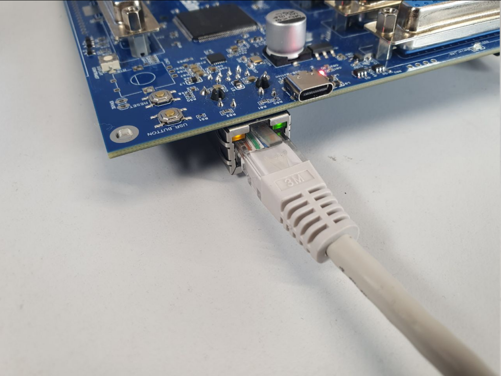
The Motion4Sim Controller has an Ethernet interface starting from PCB version 2.03. This allows it to connect to a regular LAN network via Ethernet. For the connection and setup, a standard Cat 5e patch cable or better can be used. The board supports up to 100 Mbps connection speed in full duplex. The processor runs an LWiP stack that is being improved with each update. We support DHCP. When a patch cable is plugged in, the controller attempts to establish a connection to our management servers on the internet. The serial number is encrypted and sent to the server, which then returns the license status registered there. This is how Pro controllers are authenticated to function as Pro controllers. This process is required either every 20 starts or after a period of 1 week of runtime without no connection to our servers. Basic controllers will always work, even without an internet connection. If Pro controllers are operated outside the authentication periods, they will continue to function, but the Pro features will be disabled. They will then operate with Basic licensing. Upon request, it is also possible to obtain a firmware without network functionalities for basic license.
Through the network interface, the controller now supports several new functions, including connection to the dashboard with UDP and multicast connections. It is also possible to send motion data via UDP from FlyPT Mover or DRSim Manager Motion. It has been tested and works excellently, even in the same network where multiple VR setups are operated or where there is a higher amount of traffic.
What doesn’t work well is the latency when motion data is sent from a Wi-Fi device. To work really well, we need a fairly stable transmission rate of every two milliseconds. This cannot be expected from Wi-Fi devices. However, in LAN networks, it works perfectly.
The current concept is that the motion data is simply sent to a multicast address in the network, for which the controller registers, to a specific port. This eliminates the need to determine the assigned IP address of the controller, and the data stream is received without issues. However, this does not work in networks where multiple controllers are involved. In that case, they would all listen to the same data and act simultaneously.
Currently, the dashboard is only designed for single application with one controller in the network.
How do I set up network operation?
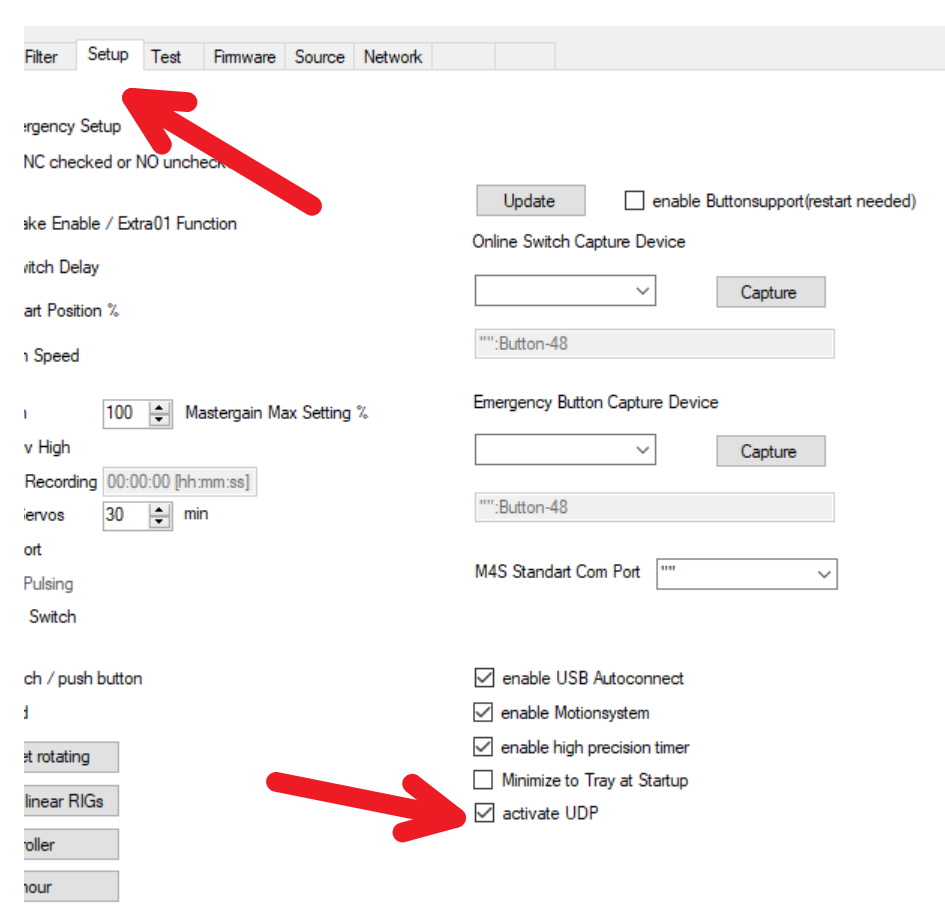
After a factory reset, the controller is set with DHCP enabled by default. In a network where DHCP is processed automatically, the network interface will be configured automatically, and there is usually nothing else that needs to be done, except for enabling the UDP protocol in the dashboard if it is being used.
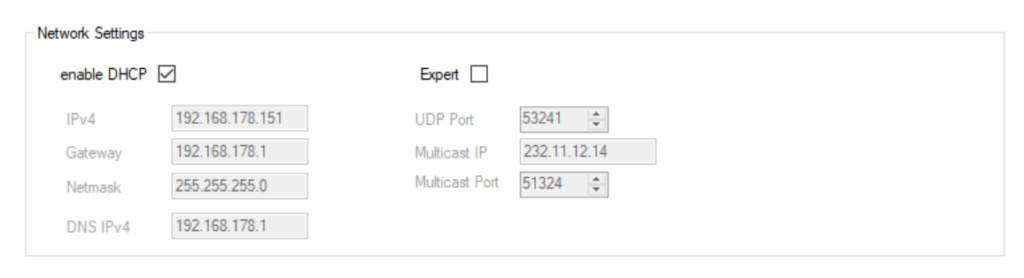
To check or modify the settings for the controller’s network, go to the Network tab. In most cases, there is no need to change any settings. Please make sure that the DHCP Enable checkbox is checked and the Expert checkbox is not activated.
When DHCP is enabled, all data on the left side, including the IP address, gateway, subnet mask, and DNS server IP address, will be automatically filled in by DHCP. If you want to change these settings, uncheck the enable DHCP checkbox. You can then adjust the settings according to your needs, but you should know what you are doing.
If you activate the Expert checkbox, you can edit all settings on the right side. These settings will be used by the dashboard and sent to the controller for it to use the same settings. It is important that the controller and the dashboard use the same data, otherwise the network traffic and communication will not work.
Once all settings have been made, the data must be sent to the controller using the Transmit button. It is important that the controller is in the Restart menu. Otherwise, a message will appear stating that the data was not transmitted. Check if the data was sent to the controller by using the Reload function in the top left to retrieve and compare the data.
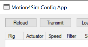
The network data can also be exported to a settings file using the Load Disk and Save Disk functions.
Setting up Network in Flypt Mover
Configuring FlyPT Mover for network is very easy. Simply open a new UDP Output module.
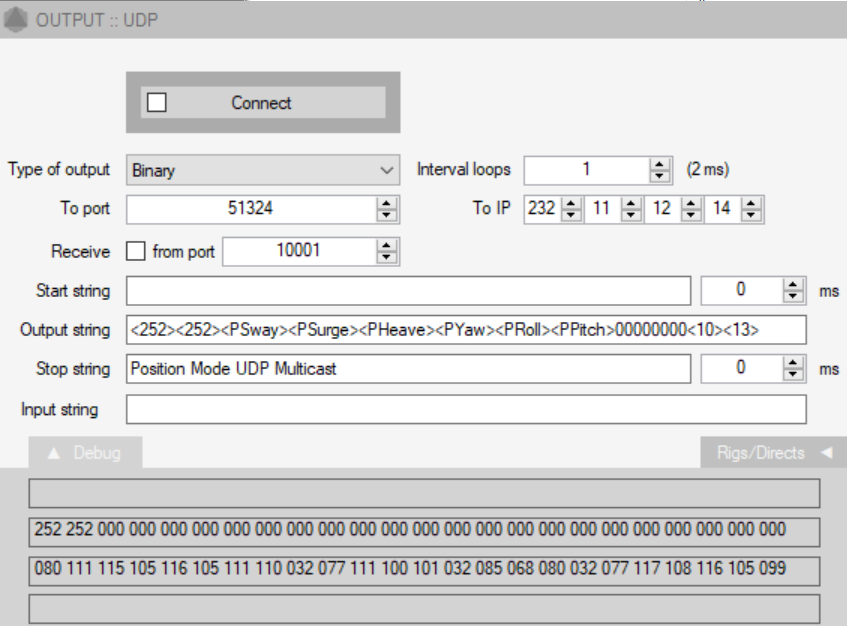
Enter the multicast address from the dashboard in the To IP field, the default selected one can be seen at the bottom of the image, and enter the multicast port in the To Port field. Then, you can configure the output string for either Direct Mode or Position Mode. This will be explained in another article. By clicking the Connect button, the motion data will be sent to the controller.
The advantage of UDP is that now FlyPT Mover and the dashboard can be operated in parallel. Please make sure to deactivate the dashboard motion if you are using FlyPT Mover separately. Otherwise, the data being sent may overlap.
Please note that if you have a network with multiple Motion4Sim controllers, it is also possible to send the motion data directly to the IP address of each controller. Change the To IP address to the respective IP address and also change the To Port to the value from the UDP port displayed in the dashboard.
You can check if the network functionalities are working by simply pinging the controller from the command line or entering the controller’s IP address in a browser. This will display a feedback response. Additionally, in the pre-start menu of the controller, if you turn the encoder to the left, the IP address will be displayed instead of the temperature if you have a Pro license.