The new PCB design can be seen in the following image. The numbers in the image indicate the various components, connectors, and pin headers. These will be explained subsequently.
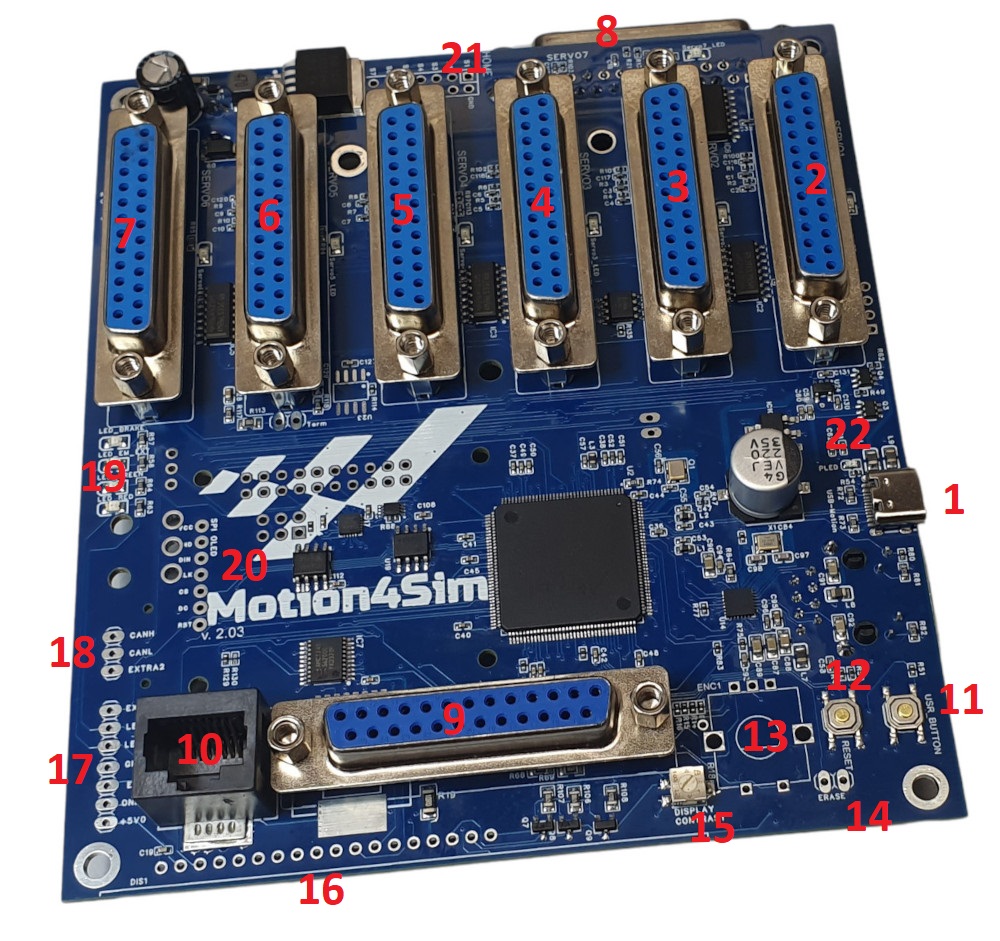
Designators for Front Side
| 1. USB Connector Type C 2. Connector Dsub25 for Servo 1 3. Connector Dsub25 for Servo 2 4. Connector Dsub25 for Servo 3 5. Connector Dsub25 for Servo 4 6. Connector Dsub25 for Servo 5 7. Connector Dsub25 for Servo 6 8. Connector Dsub25 for Servo 7 9. Connector DSub25 for Handheld Device 10. Connector RJ45 for Smart Handheld 11. User Button | 12. Reset Button 13. Pin for EC11 Rotary Encoder 14. Erase Pins for MCU 15. LCD Display Contrast Potentiometer 16. LCD Display Pin Header 17. Switches & LED Pin Header 18. Can Bus & Extra02 Pin Header 19. Status Leds 20. SPI OLED Display Pin Header 21. Homing Pin Header 22. Power Led |
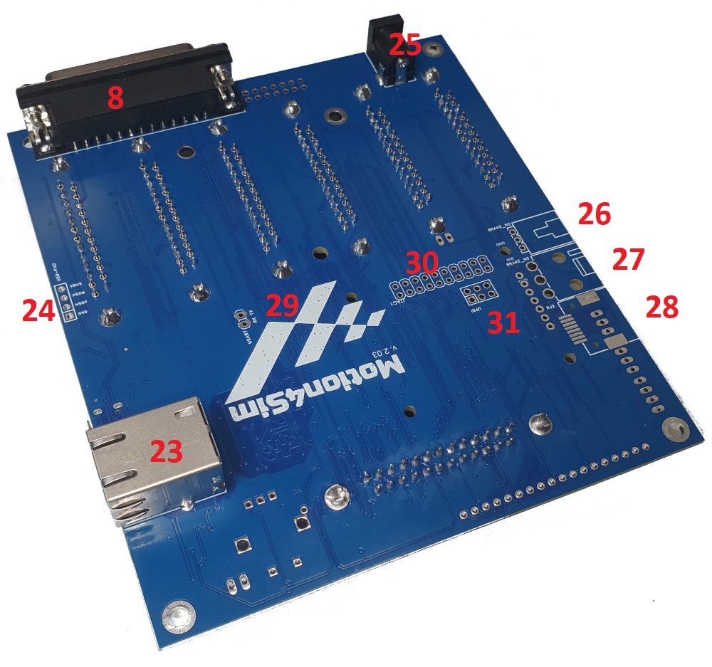
Designators for Back Side
| 23. Ethernet Connector Rj45 24. USB Pin Header 25. External Power Connector 26. Pin Header Brake Signal NC 27. Pin Header ,Brake Signal NO 28. Pin Header RJ11 undocumented 29. USART Pin Header RX TX 30. JTAG 31. UDPI |
Application and functional description of the connections and components.
1 – USB Type C connector:
This connection is used to supply the controller with 5 volts of power from the computer, receive motion data, communicate with the computer, and update and flash the firmware via this port with the software.
2-8 – Servo Connectors
These are the D-SUB25 connectors that can connect the controller to the AASD servo controllers.Please use as short cables of good quality as possible for the connection.Make sure that the cables are fully occupied and are executed 1 to 1. The length should not exceed 1 meter.
9 – Handheld Connector
This connection can be used to connect the handheld device with display and emergency stop button. It is used to control the controller and make inputs. Also, use a D-SUB25 cable here; up to a length of three meters, it works perfectly. Usage up to five meters has been proven in some cases. More info here
10 – Handheld Connector 2
This port is intended for connecting the Smart Handheld to use the emergency stop and online switches.
This connection is suitable for RJ45 cables, but please never connect an Ethernet cable that is connected to a network there. This will cause a short circuit. More info here
11 – User Button
This is the tactile push button that can be used for user inputs. It has several functions, which I will explain briefly.
1. to enter the bootloader mode required for flashing the firmware, hold down the User button and press the Reset button simultaneously or plug in the USB cable to power the controller. Then, the controller boots into the bootloader mode and is ready for flashing the new firmware.
2. If you press and hold the User button during normal operation, if you release it after four seconds, a factory reset for rotating actuators will be performed; and if you release it after eight seconds, a factory reset for linear actuators will be executed.
12 – Reset Button
The Reset button restarts the controller.
13 – EC 11 Rotary Encoder Pin Header
At this point, a rotary encoder EC11 can be mounted and soldered. It is already standardly installed on the board in the variant with display. If you have a controller that already has this encoder installed and you want to use an additional handheld, you may need to sometimes rotate the encoder by one position so that the encoder works with the handheld. Please take note of this or desolder the component.
14 – Erase Header
Please note the following information. The erase pin header is intended for erasing the MCU. Never connect these 2 pins together ! If you connect the two pins together and perform a reset or repower of the controller, the memory of the processor will be erased. You will then need to send the controller in for the manufacturer to reflash the software. Recovering is not possible at your side !!!
15 – Display Contrast
With the adjustable resistor for the display contrast, you can adjust it for the onboard display and the handheld display. Turn it clockwise for more contrast or counterclockwise for less contrast. Use a very small screwdriver and please be careful.
16 – LCD Display Pin Header
An LCD display 16×2 can be connected here, and RGB LCD displays 16×2 are also supported.
The pins D1 to D4 of the first data channel should not be connected. So, if you want to connect a display, the first six pins are occupied and soldered, then four pins remain free. For a regular display, the next six pins are used, and for an RGB display, two additional pins are required.
17 – Switches and Status Led Pin Header
On this pin header, you can connect additional contacts for the emergency button and the online switch. Additionally, there is the emergency LED and a connection for the online LED, as they are also used on the handheld.
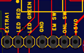
The pin layout is also printed on the board. To activate the Emergency Switch or the Online Switch, simply connect the pin to ground, and the signal will be triggered. The LEDs have the positive voltage at the pin and must be connected to ground. Extra 1 is an additional output provided for functions. The standard 2.54 mm pitch has been used.
18 – CAN BUS Pin Header
These pins are not used in the layout but offer the possibility to retrofit a CAN bus chip. This chip is also missing on the board and can be supported and used by the MCU in future firmware versions to control external CAN bus devices.
19 – On Board Status LED´s
The LED_BRAKE lights up green and indicates that the Normally Open Output is activated for the servo brakes. The LED labeled as LED_EM_EXT lights up red and indicates that the Normally Closed Output of the brake control is activated. This input can also be used under certain circumstances as an external emergency input. LED_GREEN lights up green when the controller status on the handheld is green, or LED_RED when the controller status triggers this LED. Also visible on the handheld.
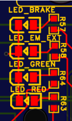
LED Brake and LED EM External are connected to the pins of the corresponding connectors 26 and 27.
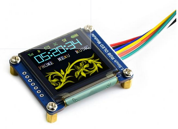
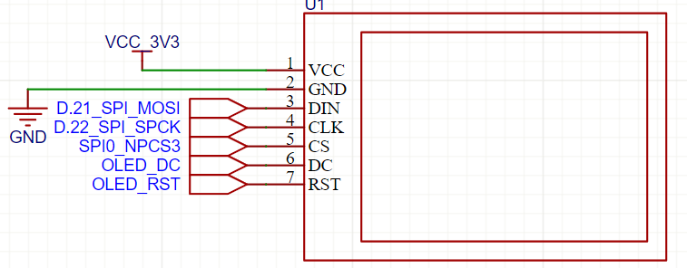
20 – SPI DISPLAY PIN Header
On this Pin header a 1.5″ 128×128 OLED Display Modul, RGB, SPI Interface can be connected
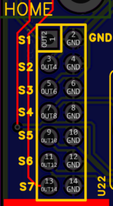
21 – Homing Pin Header
Additional external sensors for the homing process can be connected to this pin header. Simply connect the pin of the respective servo motor to ground. This pin is also directly connected to the DB25 connector.
In simple terms, during the homing process, the servo motor moves in the opposite direction towards the lower actuator end, usually waiting for the signal to be switched to ground. When this happens, it changes direction and moves towards the starting point of the defined actuator position.
Within the AASD servo, this is implemented through the so-called SIGOUT2 port, which switches the signal against ground when a certain torque is applied to the motor. Therefore, we use a hard resistance against which the actuator moves. The height of the resistance can be set in the servo driver PN24 in percentage.
If you want to use an external sensor, such as limit switches, simply connect, for example, S1 on one side and ground on the other side. When the actuator drives against this limit switch and connects it, the signal will be triggered.
5-volt-compatible inductive proximity sensors can also be used. Additionally, they require 5 volts from the board. https://www.cytron.io/c-sensor/p-5vdc-inductive-proximity-sensor-npn-no
the brown cable switched to gnd when metall is detected blue is for +5V and black for gnd
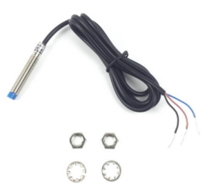
5VDC Inductive Proximity Sensor NPN NO
22- Power Led
This LED lights up in red when a power source is connected to the board.
23 – Ethernet Connector
Connect your local network, your LAN, to this port using an RJ45 Cat5 patch cable. Your router should support DHCP for proper functioning. You can also configure the IP settings via the software. It is necessary for your router to support multicast. Speeds upto 100 Mhz are supported. For the “Pro” Boards, it is necessary that they also have a connection to the internet at regular intervals to autheticate the device. Only the serial number of the device is transmitted for this purpose, enabling authentication.
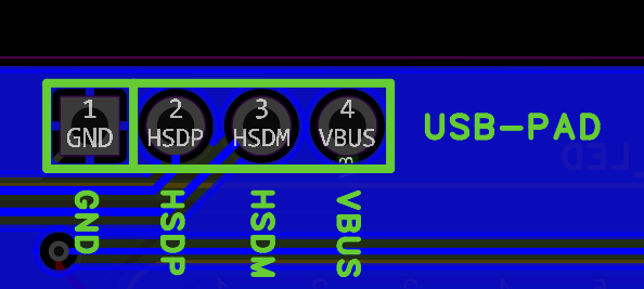
24 – external USB Pin Header
You can connect an additional USB cable to this pin header, possibly for mounting the controller in a case. The marked pins lead directly to the processor. The connection should be USB 2.0 compatible, meaning that a USB-C connection will not work as the corresponding resistors are not present or should added externally.
25 – External Power Connector
You can connect an external 12-volt, 1-amp power supply to this port. This way, the controller will be safely powered by an external power source and should function properly. Common plugs. The plug should be 5.5 x 2.1 mm in size.
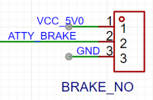
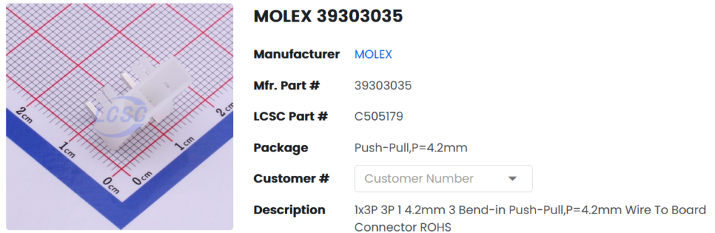
26 – Brake Connector 1
You can connect a relay for a servo brake to this signal. It operates on the way setup in software Normally Open or Normaly closed principle. This pin can draw 20 mA only.
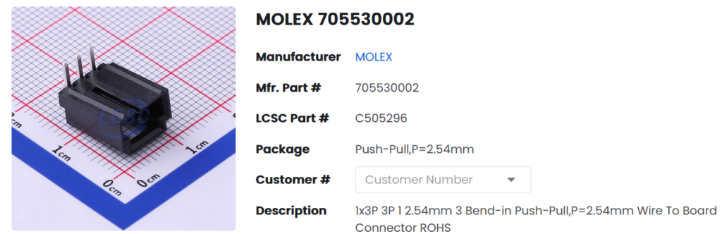
The corresponding Molex connector can be connected and soldered to this pin header, or you can also solder the connections directly.
27 – Brake Connector 2
You can connect a relay for a servo brake to this signal. It operates on the way setup in software Normally Open or Normaly closed principle. This pin can draw 20 mA only.
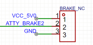
The two connectors for the brakes switch in opposite directions. This means that for Normally Open, one has voltage while the other does not, and vice versa. This setting can be swapped in the brake setup.
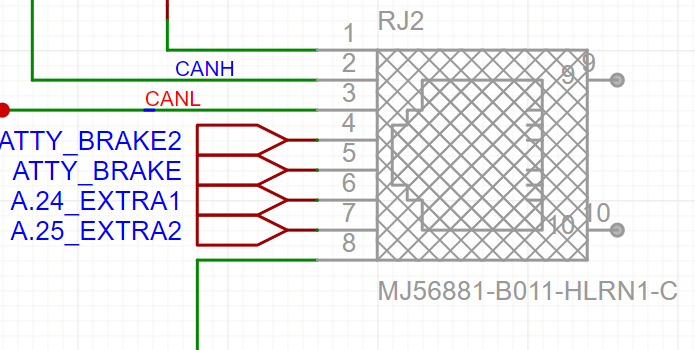
28 – Brake /Can Bus Connector
An SMD RJ45-compatible connector can be soldered to the soldering point for this connector, which is not standardly installed, providing support for the two CAN bus lines as well as Extra 1, Extra 2 of the servo controller, and the two brake signals. Can Bus is not provided in this Version
29- UART Pin Header
RX and TX of a 3.3-volt UART can be connected to this pin header. For example, this allows for the use of an external FTDI USB Serial Converter.
For this purpose, simply use an FTDI 232 Serial to UART Converter, bend the two RX and TX pins upwards, and solder them into the pins. The board should align fairly closely with the outside of the controller. Please note and do not confuse, RX and TX are then reversed as usual.
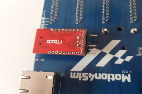
Further applications in the future may also allow for the connection of other UART components, such as a 9DOF-Racer iMU, to evaluate acceleration signals.
30 – JTAG Interface
for debugging and programming
31 – UDPI Interface
for debugging and programming
Please advise on Your 6DOF controller how it can interface with x-Plane 10/11 do You have this interface? What is the max load factor? And what is the Price. Please advise. Thanks